Tackling Non-Ideal Cases with the Digital Workflow
As dental technicians, we are all accustomed to receiving implant cases that are less than ideal. Sometimes we question the doctor’s choices. The truth is we do not know the treatment difficulty or the quality of the patient’s bone that may have required a less-than-ideal implant placement position. In addition, the patient’s finances might dictate the final treatment plan. There are multiple variables that can come into play and we must learn how to work with these variables to provide the patient with the best care possible.
With the rapid progression of dental technology, it can seem impossible to keep up with all the new design techniques especially when working with less-than-ideal situations. Doctors ask for a digital workflow and many labs are comfortable designing straightforward cases, but not all cases are routine. What does a lab do when they receive a case that is not straightforward? As the head of Design Services at Argen, an industry-leading manufacturing and milling center, the most common question I get is “But Trevor, what can we do?” I must admit, at times I look at the case and think, “How is this going to work?” Then I remember one key benefit about the technology we so often fear - I can always just hit the undo button.
Let us look at an anterior case I recently worked on with a lab (Fig 1). The doctor provided the lab with conventional maxillary and mandibular impressions and the patient’s existing partial denture. The lab scanned the case using a 3Shape desktop scanner and exported the file to Argen for help with design. For this case, we worked with two 4.3/5.0 RP Nobel Active implants that became the foundation of a 6-unit fixed prosthesis from #6-#11.
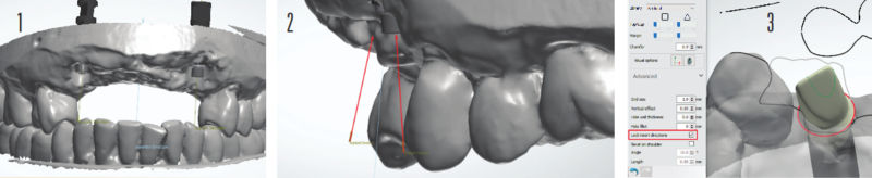
Due to the non-parallel angulation of the implants(Fig 2),we had to decide between four possible restorative options in consultation with the treating doctor and the lab technician. The four options were:
1. A screw-retained bridge using multi-unit abutments
2. A screw-retained bridge with one engaging abutment and one non-engaging abutment
3. A screw-retained bridge over two non-engaging abutments
4. A cement-retained bridge over two engaging abutments
Initially, we decided on a screw-retained bridge using two non-engaging abutments, but we had some concerns. We were working with only two implants and four pontics (Fig 2), so there was potential for excess stress on the screws because the hexagon platform would offer no additional support with non-engaging abutments. We also considered one engaging and one non-engaging abutment. Our main goal was to provide the patient with an aesthetically pleasing restorative solution that would last. Ultimately, we all agreed that the cement-retained bridge over gold anodized titanium abutments that fully engaged the hex platform offered the best solution.
Once we decided on the final restoration, we had to figure out how to design the titanium abutments and fixed prosthesis. To determine that, we asked ourselves another question: “Pink or no pink?”
Using Carl Misch’s classification of fixed prosthetic (FP) options in implant dentistry, we identified the type of case we were working with: FP-1, FP-2, or FP-3.
FP-1. Design includes only the crown to replicate a natural tooth.
FP-2. Design includes a crown with a portion of the root. Our crown design would have natural contours but because there was bone loss present, our design would require an exposed root structure to provide a natural look of a receding gum line. The technician could stain the roots darker for a more natural look.
FP-3. Design includes the crowns and gingiva as a result of extensive bone loss.
Since the patient had moderate bone loss and a low lip line, we decided to design the case as an FP-2. This choice would provide the lab with some flexibility while working with the doctor to determine the look of the final implant prosthesis. With the addition of some pink porcelain, the technician could easily convert this case from an FP-2 to an FP-3.
When working with 3Shape Abutment Designer, it is best practice to lock your insertion direction, but every now and then, it is okay to trust your eye (Fig 3).
When designing abutments, it is important to consider your margin placement and its impact on the emergence profile of your crowns. We set our margins in a location that allowed us to maintain our FP-2 design (Fig 4). Once we set the margins in a location we were happy with, our focus shifted to the portion of the abutment above the margin line, most commonly referred to in 3Shape as the “top cap.” Designing most of an abutment in the parametric step will help you achieve a proper insertion direction and maintain the basic parameters set in your control panel. However, occasionally you may have to make slight adjustments to your top cap in the sculpting step. For less experienced abutment designers I suggest refraining from doing too much sculpting as it may cause problems with the path of insertion and during milling once, the design has been completed.
A technician’s amazing ability to see all the fine details can be both a blessing and a curse when designing crowns using CAD software. It is very easy to fall into the trap of worrying about every little detail. “This embrasure doesn’t look right,” or “It looks a little under contoured,” are common concerns. Instead, smile because you have just completed the daunting task of designing your abutment. The rest will fall into place.
For our case, we began with the centrals and worked our way toward the posterior. This process limited the number of adjustments needed. The major concern at that point was aligning the canines to the abutment, and since the alignment was not perfect, we had to create an illusion for when the patient smiles. To maintain the integrity of the crown we placed, we designed the root at an angle that had a smooth transition to the abutment (Fig 5).
Designing an artificial root can be intimidating, but remember, you can always hit the undo button. When designing in 3Shape, I recommend using the individual morphing tool more often than not. The individual morphing tool assists in maintaining the general anatomy of the library you have selected while giving you the most natural look.
Once we attached the margin lines to the abutments, we angled the restoration so we had a profile view of our design. Most people know that you can change the size of the radius when using the individual morphing tool, but you can also change the length at which that radius will have an effect on your design. By highlighting the edge of your design, you are activating the silhouette morph function of the tool, which will give your design a much more proportional look. Fig 6 demonstrates the proper tool placement needed to activate the silhouette morphing tool and Fig 7 shows the way the different morph functions affect your design. Once this is set, I then feel comfortable using my wax knife tool to sculpt and design the root (Fig 8).

I recommend keeping the wax knife at a lower intensity and refraining from making multiple clicks. This tool should be used for one smooth motion to create a nice transition from root design to crown design. These same principles can be applied when designing your gingival third to create a more designed look. At this point, you can now let the artist in you shine.
After designing the roots, we took one last long look at the case and challenged ourselves to pinpoint an issue with the design. There it was right in front of our eyes - the exposed abutment design (Fig 9). The implant on #11 was placed supra gingival due to the significant bone loss, which prevented us from designing our abutment margin lines sub gingival. We decided to sculpt more around the gingival to provide the technician with more support for pink porcelain (Fig 10). There was still concern about the metal from the titanium abutment showing on the facial, so we included a gingival flange 0.30mm off the tissue to minimize a food trap (Fig 11).
This case presented challenges with line angles and the crowns not aligning perfectly to the implants, but with one light sculpting the design was ready to be milled with Argen’s HT+ Zirconia (Fig 12). You could ask a thousand different technicians about how they design using CAD software and you will receive a thousand different tips and techniques. This is because, as technicians, we need to feel out what is best for each specific case. At its core, though, the design principles are the same.
When trying to obtain a certain look for crown designs, it is common for technicians to “overdesign,” which results in a distorted appearance. It is amazing how easy the digital workflow can be when you aim to simplify your design steps. Less is more. The goal is to create proper spacing, manipulate your design to have the necessary presence in the mouth, and fine-tune your design. The libraries of each design software are there to assist you in achieving the most natural look possible. Use them to your advantage.

Article originally published in IDT: https://nadl.org/journal-dental-technology/